Teaching MS? Download Material to Be Used in Presentations!
If you are teaching mass spectrometry courses you may find it useful to have some of the photographs and charts used in Mass Spectrometry – A Textbook at hand. Now, here is support for instructors. Most of these photographs and charts are exhibited in the printed book while a few others are presented here as a bonus.
Figures that are new in the 3rd edition are marked with a NEW tag.
Of course, only material prepared by the author alone can be offered for download here, while third party-material is not included for copyright reasons. Some of the photographs may vary slightly from the printed version in that they have no lettering or show slight differences in scale or crop. All photographs are supplied at a size suitable to be included in fullHD presentations (mostly JPGs, 1500 px long side). The pictures are collected in the order of their appearance in the 3rd edition of Mass Spectrometry – A Textbook along with figure numbers and (abbreviated) legends.
Material from this page may be downloaded for non-commercial educational purposes and be used free of charge as long as the copyright mark is not removed. Click on the preview pictures to enlarge to full size. Then use right mouse button to open the “save image menu” of your browser.
Chapter 1
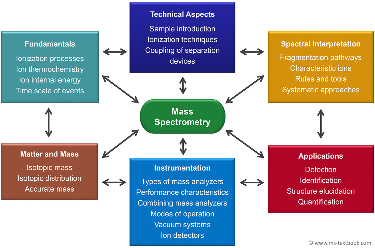
Fig. 1.3 NEW The many facets of mass spectrometry. Each aspect is closely related to the others in
various ways. Their assemblage yields an impression of the dimensions of MS.
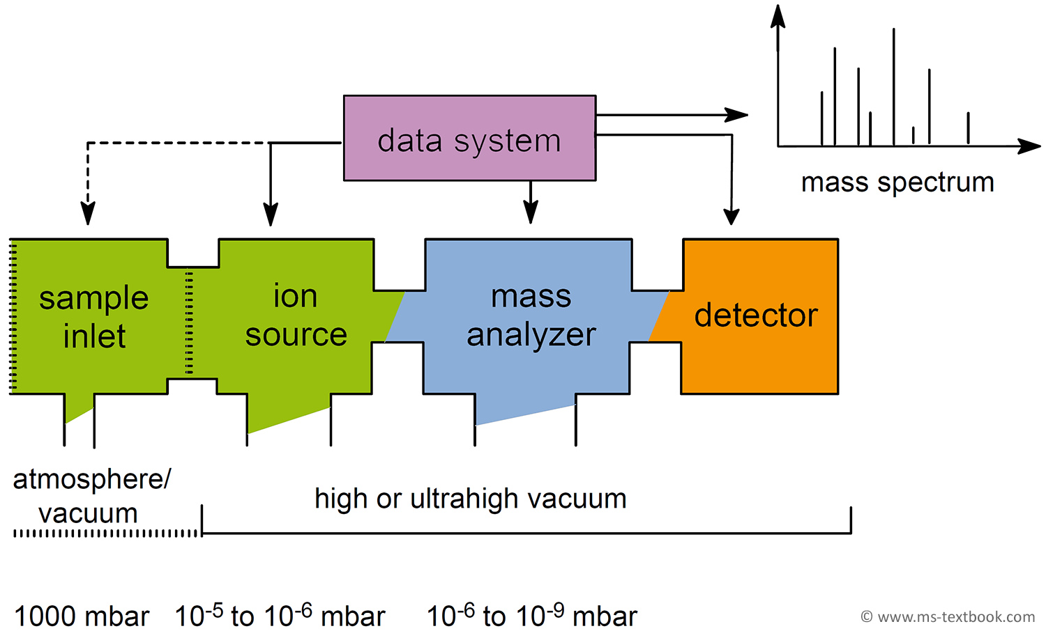
Fig. 1.5 NEW General layout of mass spectrometers. Several types of sample inlets can be attached to the ion source housing. Transfer of the sample from atmospheric pressure into the high vacuum of the ion source and mass analyzer is accomplished by use of a vacuum lock.
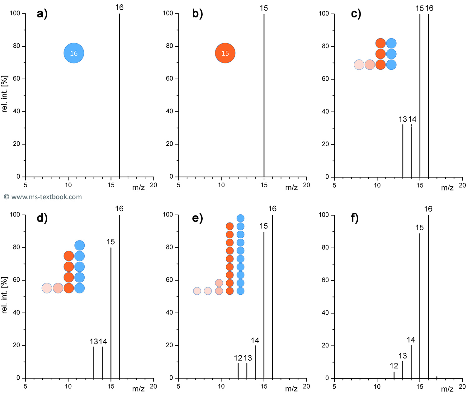
Fig. 1.7 NEW Statistical nature of mass spectra and the appearance of methane spectra based on very low numbers of ions. (a) and (b) by one ion, (c) by eight ions, (d) by eleven ions, (e) by 23 ions, and (f) by thousands. The isotope peak of 1.1% relative intensity at m/z 17 is only visible and meaningful in the case of (f).
Chapter 3
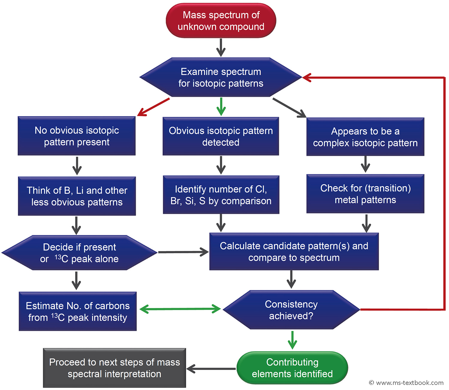
Fig. 3.17 NEW Guideline for the identification of contributing elements based on isotopic pattern
analysis.
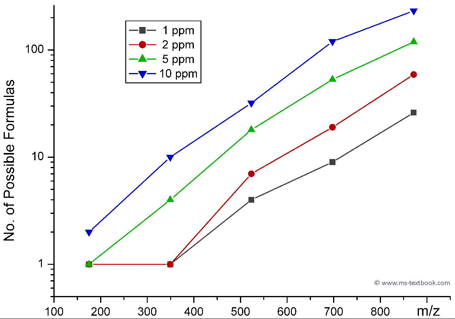
Fig. 3.26 NEW Number of possible even-electron ionic formulas based on a free selection among the elements C, H, N, O as a function of relative mass error vs. m/z. The data points correspond to [(arginine)1–5 + H]+ cluster ions, m/z 175.1189, 349.2309, 523.3427, 697.4548, and 871.5666.
Chapter 4
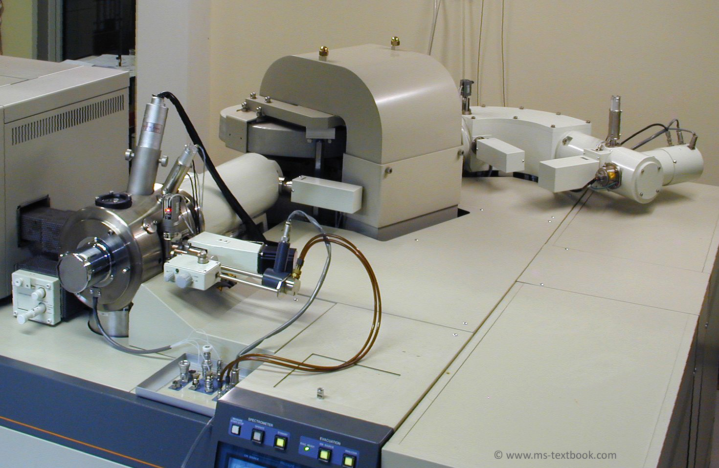
Bonus JEOL JMS-700 double focusing magnetic sector instrument.
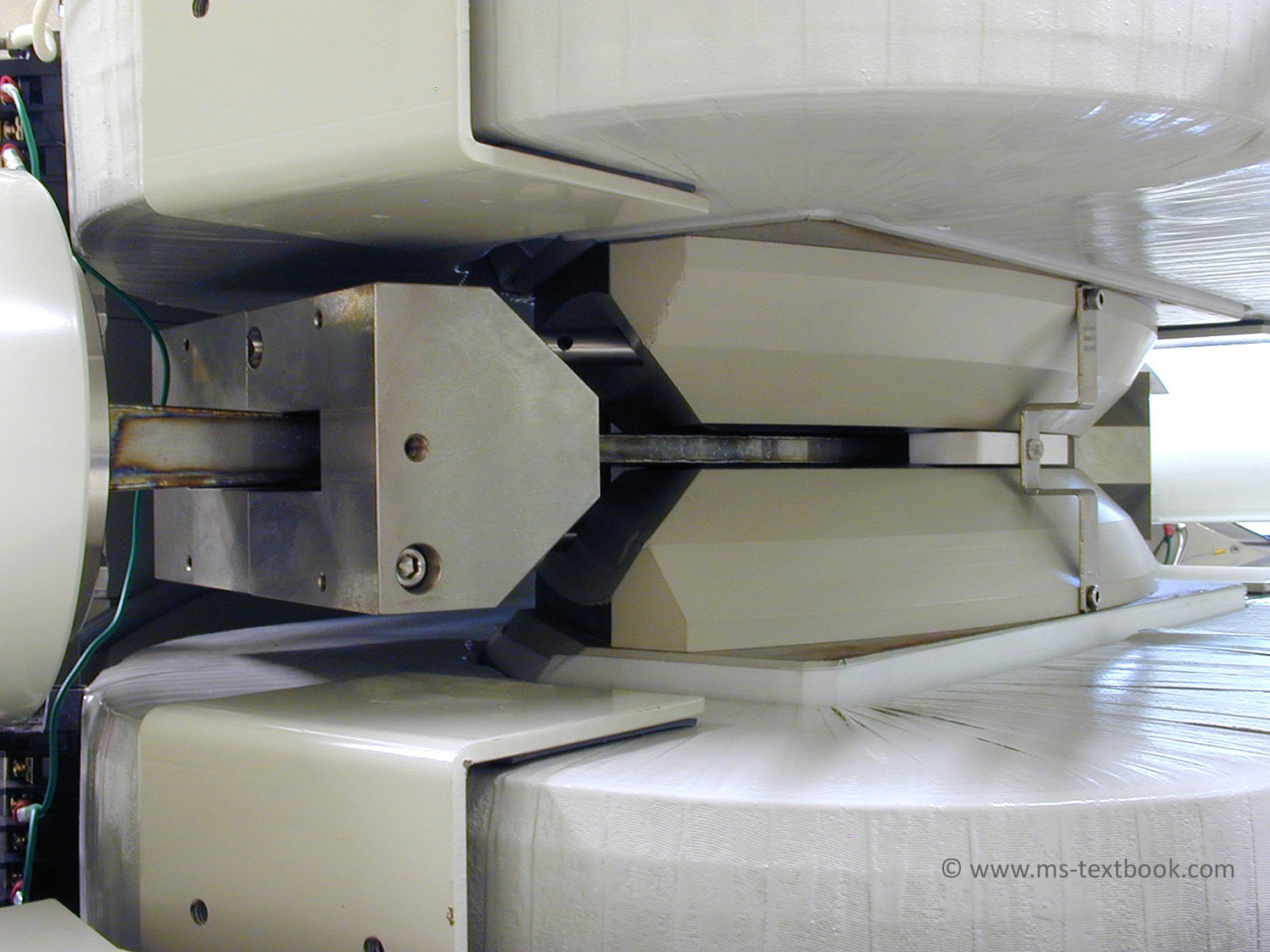
Fig. 4.28 Flight tube passing through the gap of the magnetic sector of a JEOL JMS-700 instrument seen from the ESA side. The shapes of the pole pieces of the yoke and the additional blocks around the tube are designed to minimize fringing fields. In addition the pole faces are rotated to increase the mass range.
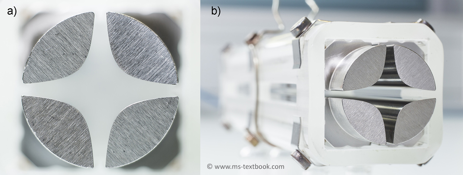
Fig. 4.37 NEW Linear quadrupole with hyperbolic rods. (a) Head on view showing the cross section of
the rods and (b) whole device partially revealing the polished inner surfaces.
Fig. 4.40 NEW RF octopole ion guide used to bridge a differential pumping stage of an ESI interface in a Finnigan LCQ instrument. (a) Head-on view to show the octopole alignment and (b) side view.
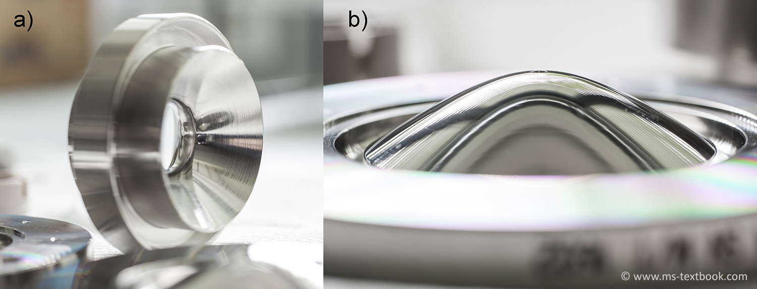
Fig. 4.53 NEW Electrodes of the Finnigan LCQ quadrupole ion trap analyzer. (a) Ring electrode with symmetrical hyperbolic cross section of the inner walls of the ring. (b) One of the pair of hyperbolic end cap electrodes.
Fig. 4.62a NEWAnalyzer maintenance of a QIT; here of the Finnigan LCQ. Complete QIT analyzer
mounted onto the top cover plate of the vacuum manifold.
Fig. 4.62b NEW Analyzer maintenance of a QIT; here of the Finnigan LCQ after taking it apart for cleaning.
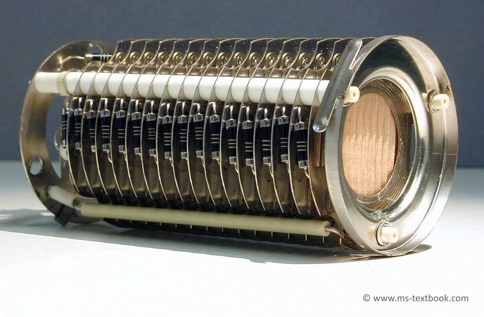
Fig. 4.93 Discrete dynode electron multipliers. An old-fashioned 16-stage Venetian blind-type SEM clearly showing the resistors and ceramics insulators between the stacking dynodes at its side.
Fig. 4.95 Channeltron multiplier. Ions or electrons from a conversion dynode would enter from the left side. Amplification of secondary electrons occurs down the bent tube.
Bonus Rotor of a small (70 l/s) turbomolecular pump.
Chapter 5
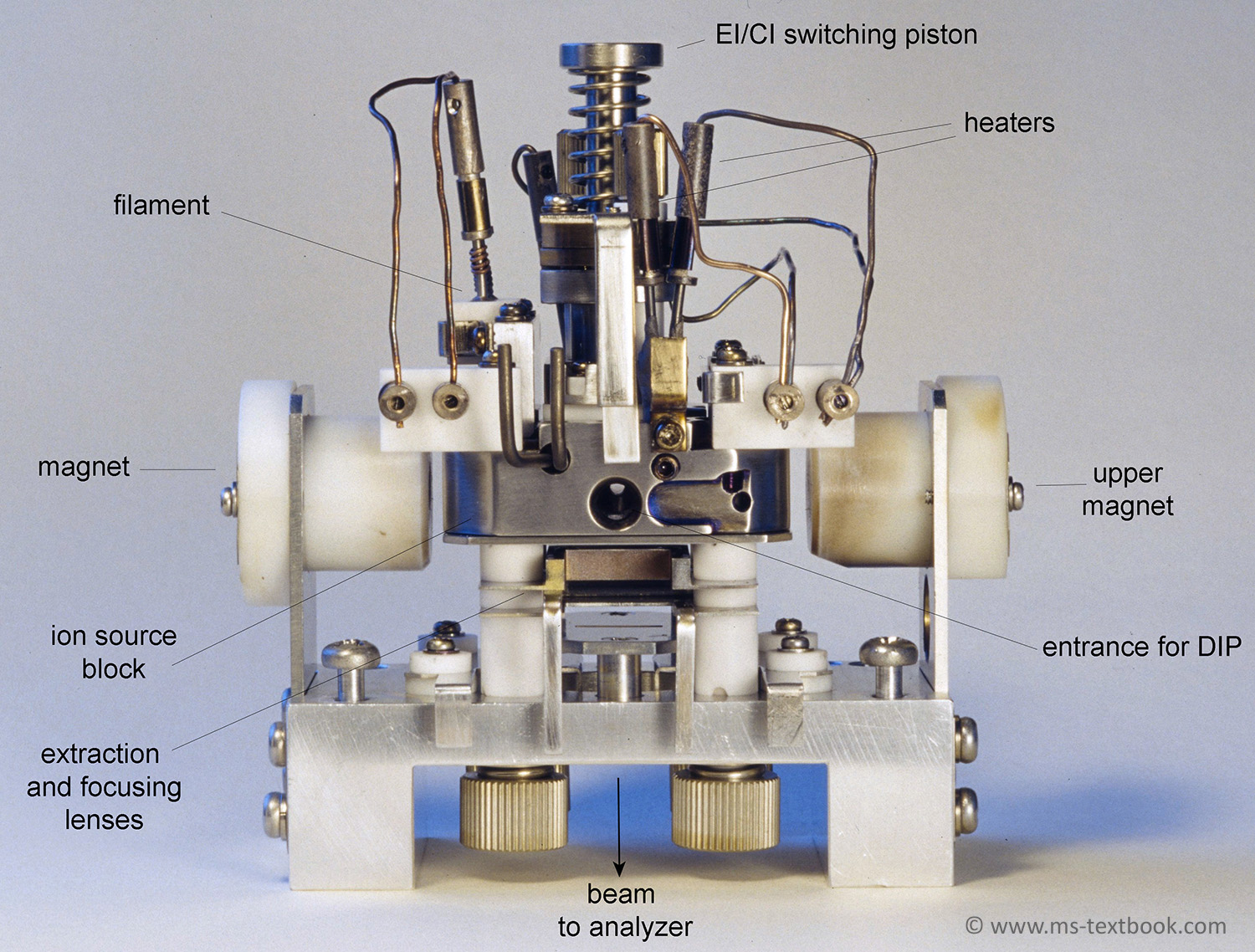
Fig. 5.2 EI/CI/FAB combination ion source of a JEOL JMS-700 sector instrument.
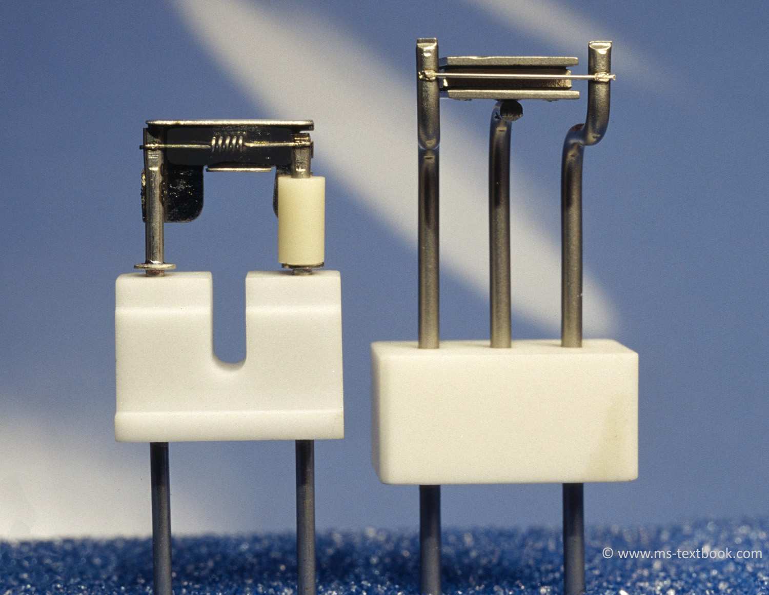
Fig. 5.3 Filaments for EI/CI ion sources. A coiled filament of the VG ZAB-2F (left) and a straight wire filament of the JEOL JMS-700 (right). The shields behind the filament are at the same potential as the wire itself and the white parts are made of ceramics for insulation.
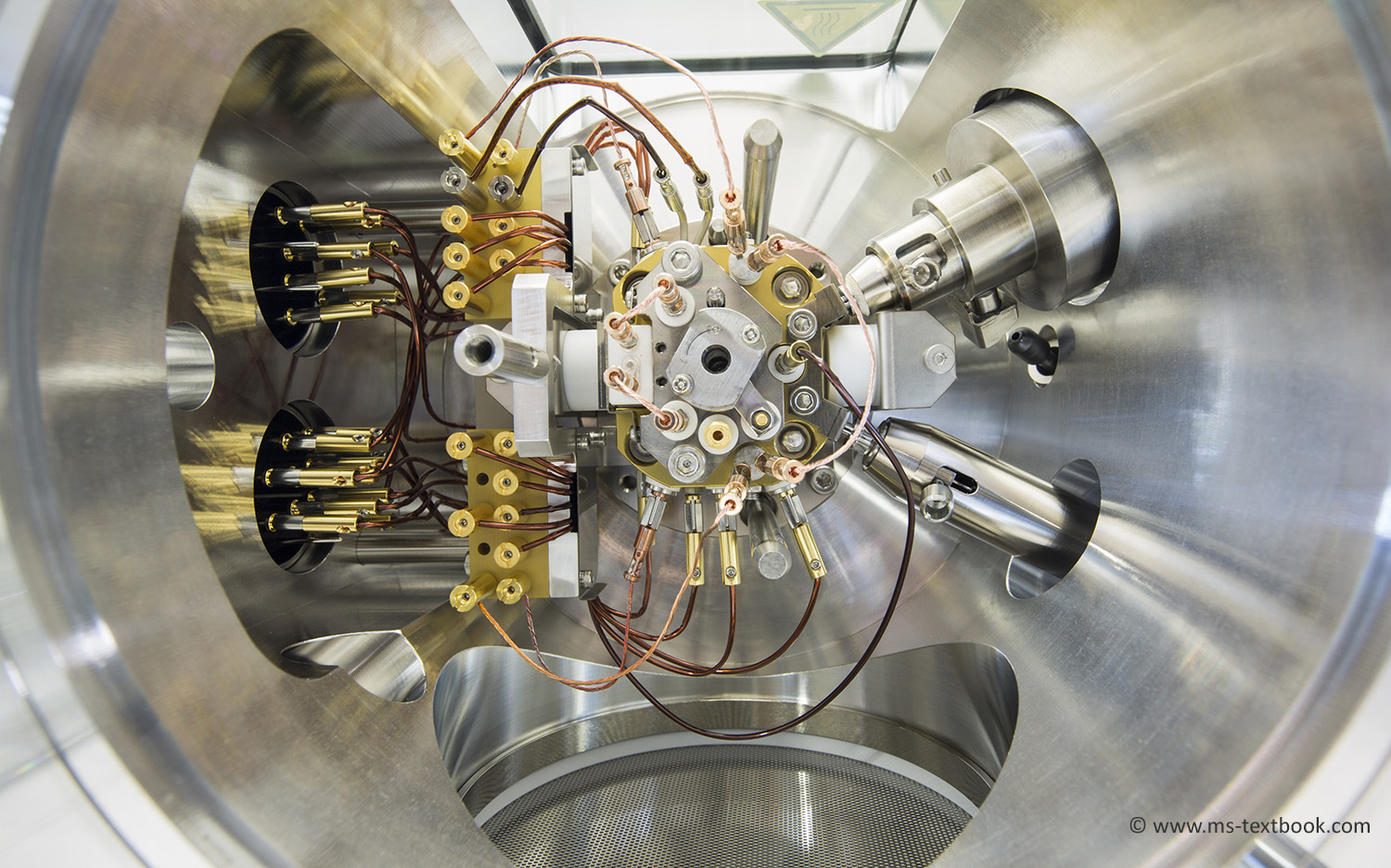
Fig. 5.5 NEW Also cover photograph. An EI source mounted in the ion source housing of a JEOL AccuTOF GCx instrument. All voltages for operation are supplied via vacuum lead throughs from the left side. A connector to a gas chromatograph reaches down from the upper right while a connector to the reservoir inlet enters from the lower right side. The turbomolecular pump of the ion source housing is located directly below the protective wire mesh on the bottom.
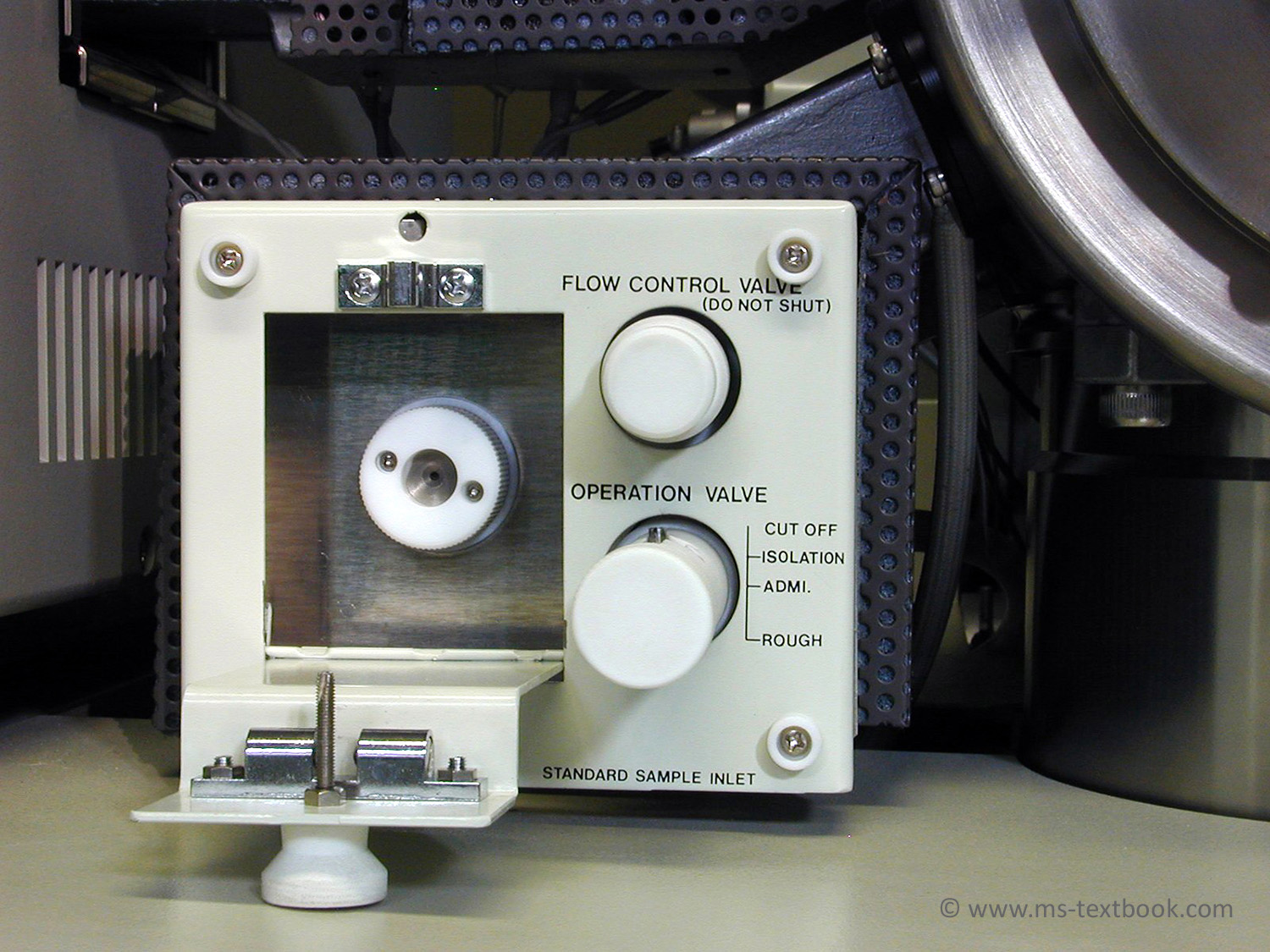
Fig. 5.6 Reservoir inlet of a JEOL JMS-700 sector instrument with the septum injection port opened. The “operation valve” switches between evacuation, isolation, and admission of the sample; a needle valve allows regulation of the sample flow. The GC transfer line crosses in the upper background from the GC (left) to the ion source housing (upper right).
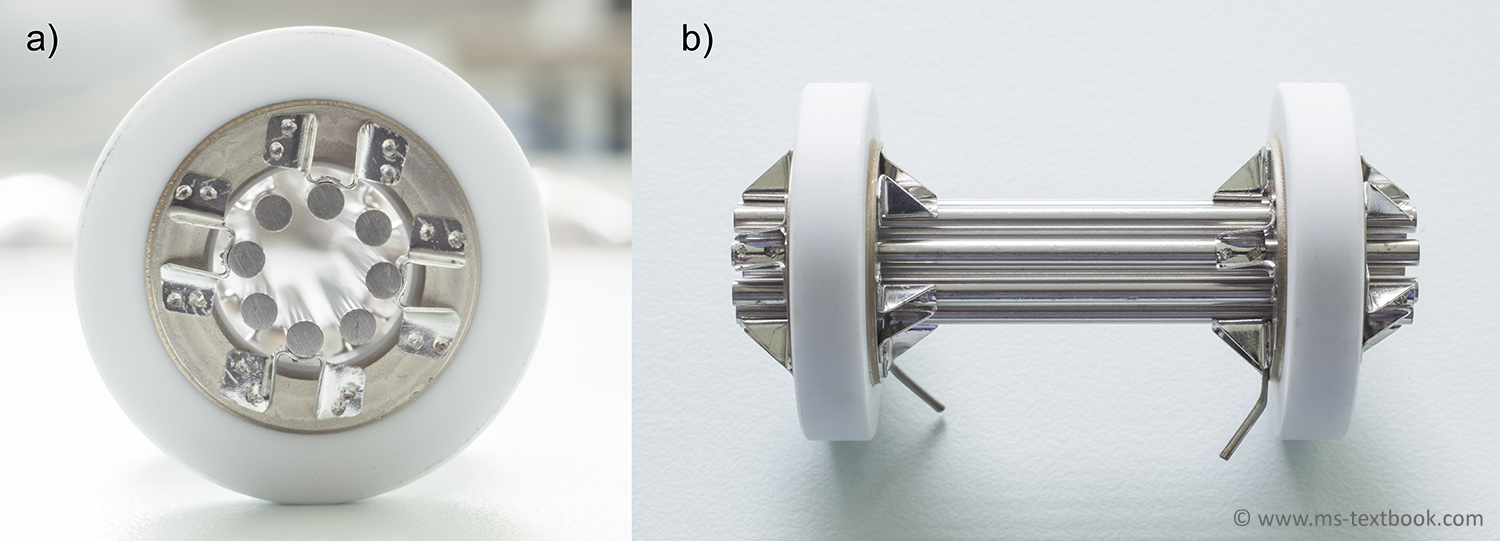
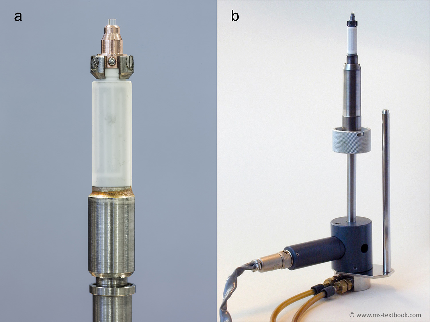
Fig. 5.7 Direct insertion probe (DIP) for use with EI, chemical ionization (CI), and field ionization (FI). (a) The copper probe tip holds the glass sample vial and is fitted to a temperature-controlled heater. The heater, a thermocouple, and cooling are provided inside. The (white) ceramics insulator protects the operator from the high voltage of the ion source. (b) Entire DIP of a JEOL JMS-700 equipped with water cooling.
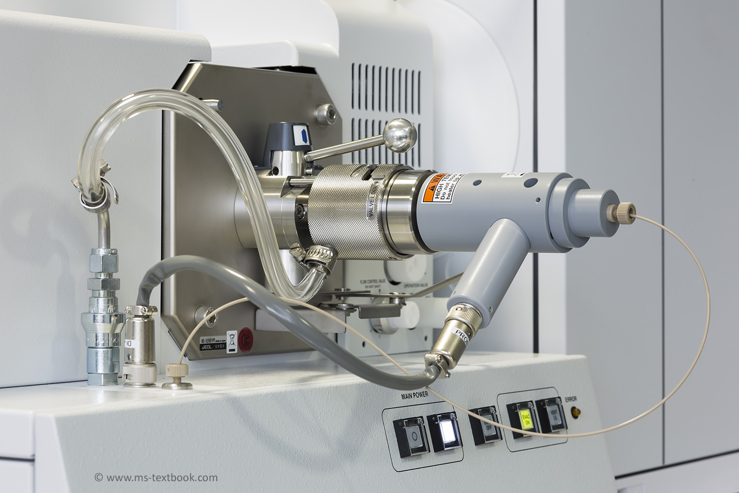
Fig. 5.9 NEW A direct insertion probe on a JEOL AccuTOF GCx instrument. The probe is shown in its fully inserted position. The transparent hose (left) provides rough vacuum to the lock before insertion of the probe, the gray cable connection serves for heater power supply and temperature control, and the light brown capillary delivers pressurized gas for cooling the probe tip if required.
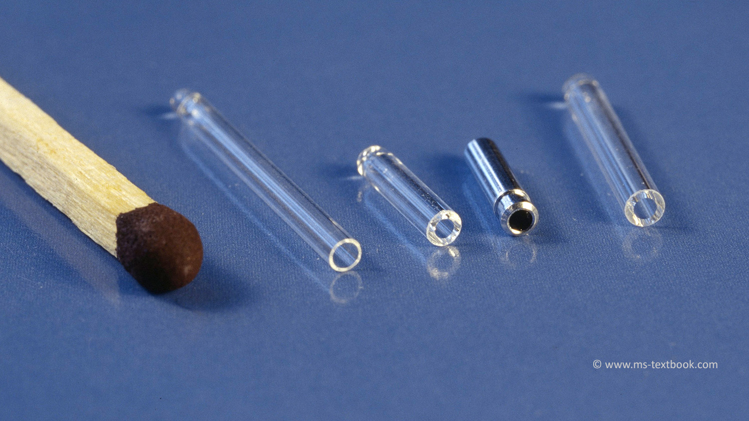
Fig. 5.10 Sample vials for different DIPs. From left: VG ZAB-2F, Finnigan TSQ700 glass and aluminum version, and JEOL JMS-700. The match illustrates the scale.
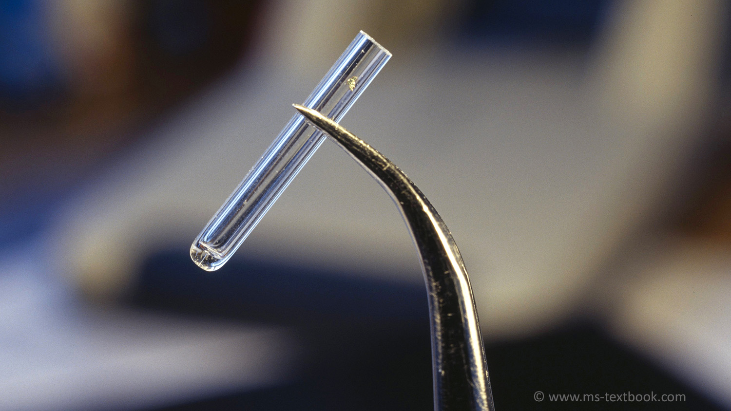
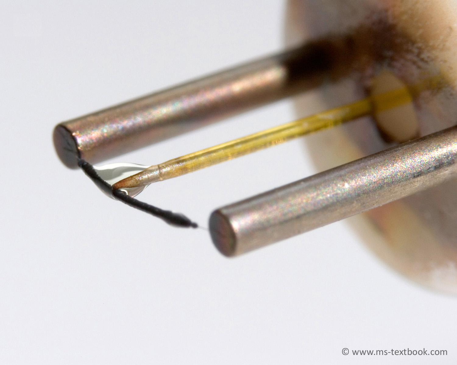
Fig. 5.11 Sample vial loaded with some analyte. The bright yellow speck halfway between the tip of the tweezers and upper rim of the vial is the solid material to be analyzed.
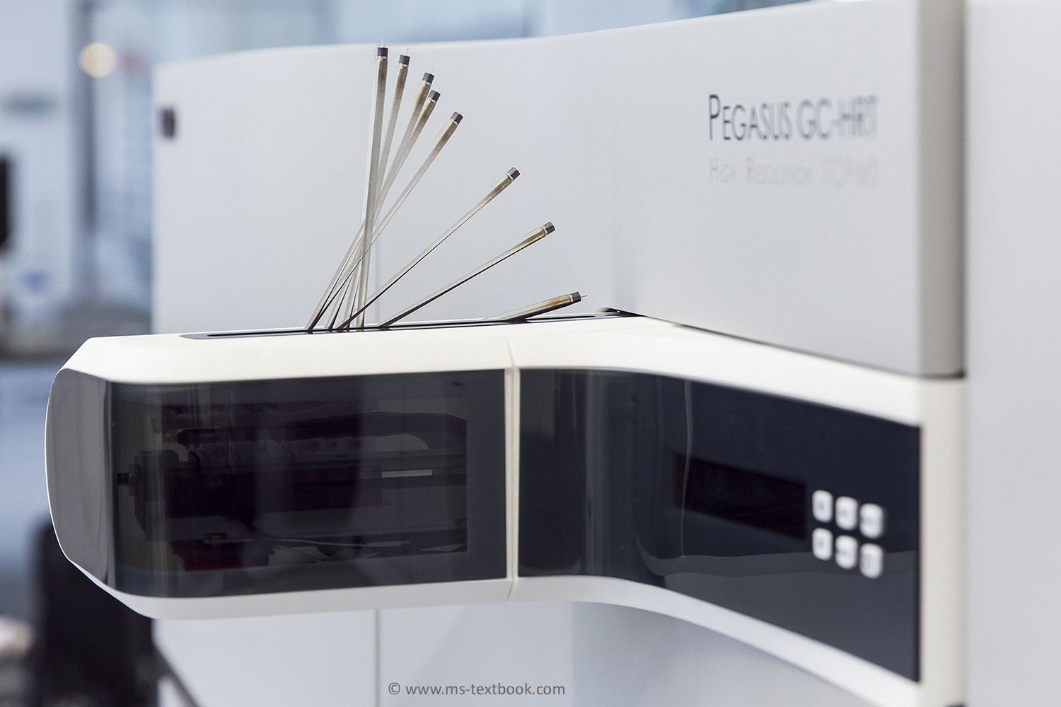
Fig. 5.13 NEW Automated DIP in operation as visualized by multiple exposures. After having received the sample vial in vertical orientation, the rod is driven to the left and tilted downward for insertion through the lock. The photograph shows the SIM DIP mounted to a LECO Pegasus GC-HRT instrument.
Chapter 7
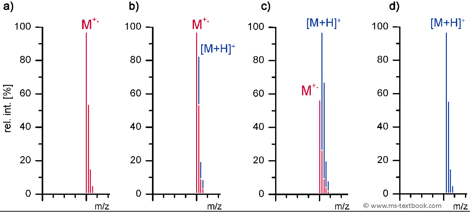
Fig. 7.2 NEW Stepwise change of signal appearance upon transition from pure molecular ion formation (red peak portions) to protonated molecules (blue peak portions). (a) Pure molecular ion peak with correct isotope pattern, (b) some contribution of [M+H]+ causes an excessively intensive [M+1] peak, (c) mostly [M+H]+, and (d) pure [M+H]+ ion signal with correct isotope pattern. Only pure M+• and pure [M+H]+ result in undistorted isotope patterns
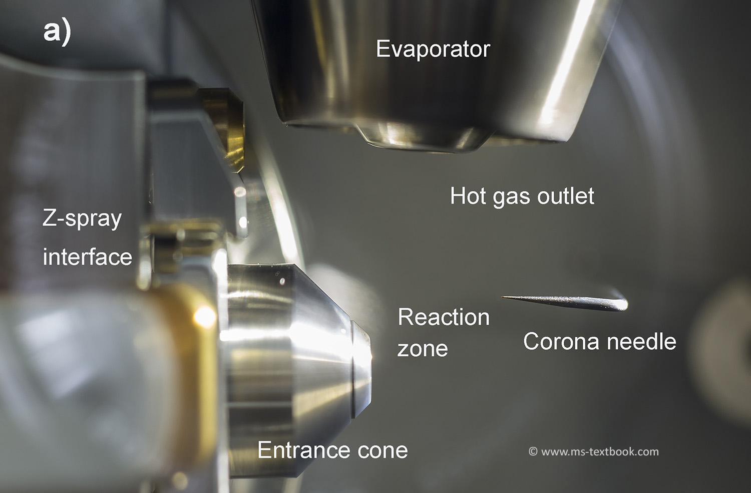
Fig. 7.22a NEW APCI source of a Waters SQD2 instrument attached to a Z-spray interface.
Fig. 7.22b NEW APCI source of a Waters SQD2 instrument attached to a Z-spray interface. APCI source as seen in operation. The blueish corona discharge corresponding to about 10 μA discharge current at the tip of the needle is only visible in virtual darkness.
Chapter 8
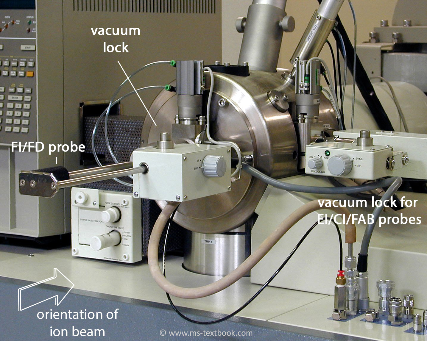
Fig. 8.4 FD probe inserted into the vacuum lock. FD probes are generally inserted in axial position to free the vacuum lock of the DIP for FI use. The emitter wire is now oriented vertically to comply with the beam geometry of the magnetic sector analyzer.
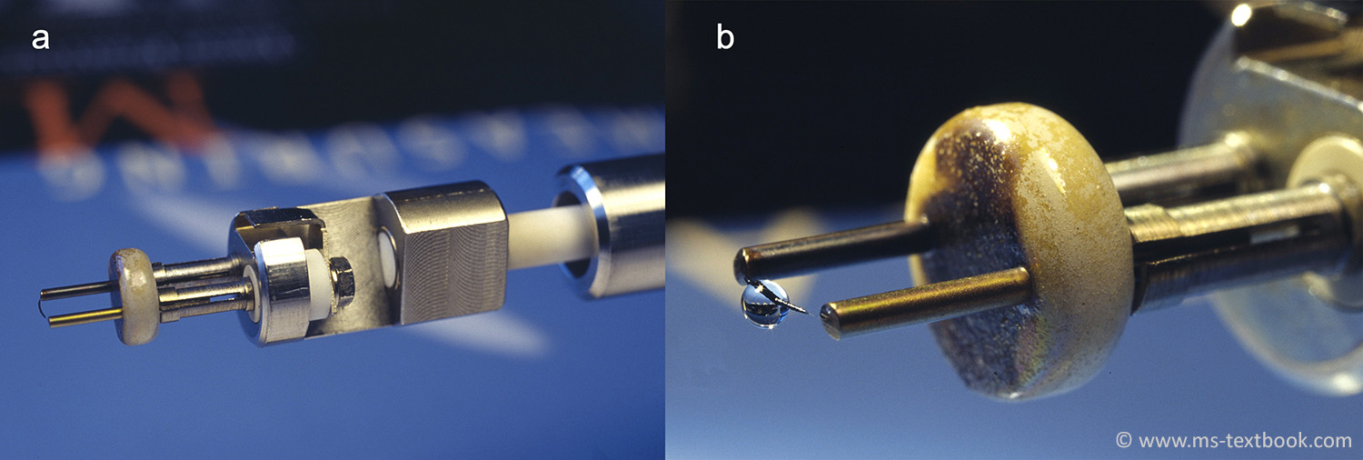
Fig. 8.8 FD probe. (a) Emitter holder of a JEOL FD probe tip, (b) a drop formed of 1–2 μl of analyte solution placed onto the activated emitter by means of a microliter syringe.
Fig. 8.23 LIFDI: wetting of the emitter with solvent spreading out over the activated zone. The 13-μm tungsten wire
connecting this section to the posts is barely visible.
Chapter 9
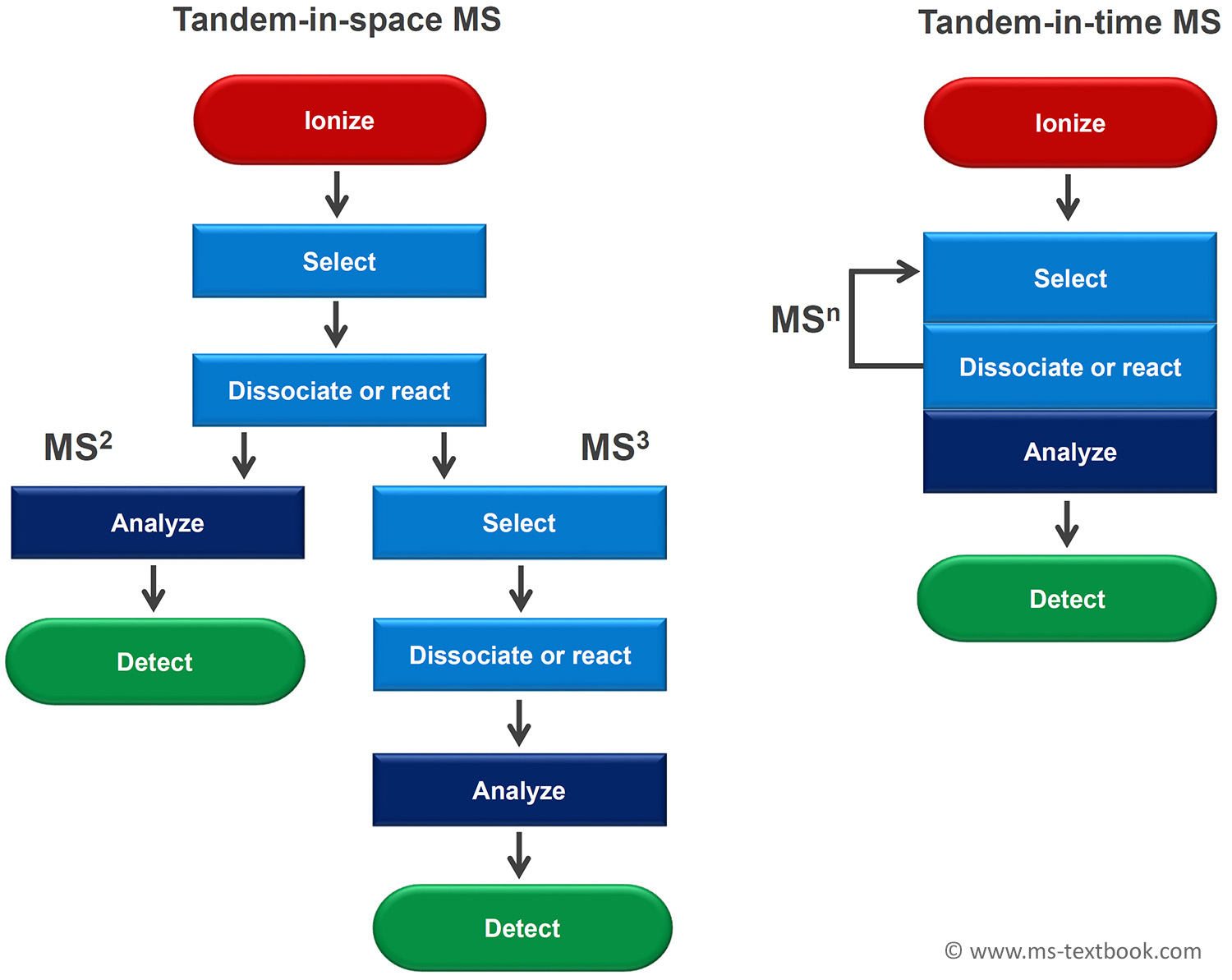
Fig. 9.1 NEW Comparison of tandem-in-space and tandem-in-time MS. Obviously, higher order MSn can be better realized by tandem-in-time setups, whereas tandem-in-space instrumentation is usually designed for MS2 with MS3 representing already the rare exception.
Chapter 10
Fig. 10.6 FAB probe of a JEOL JMS-700 magnetic sector instrument (left). The probe tip with a drop of glycerol placed onto the exchangeable stainless steel FAB target (right).
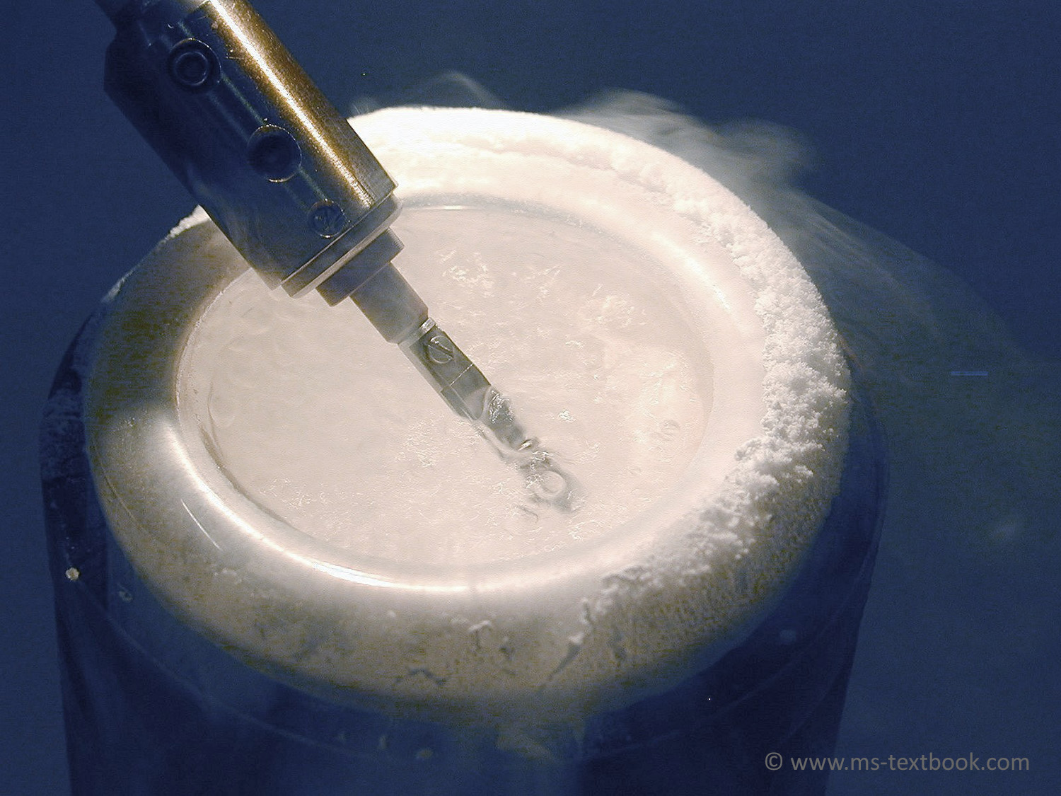
Fig. 10.18 NEW Getting ready for LT-FAB by immersion of a FAB target with sample solution into liquid nitrogen. After about 30 s the solvent matrix is deeply frozen and the tip is cooled to allow for transfer of the probe into the vacuum lock and further into the ion source whilst avoiding untimely thawing of the solvent.
Chapter 11
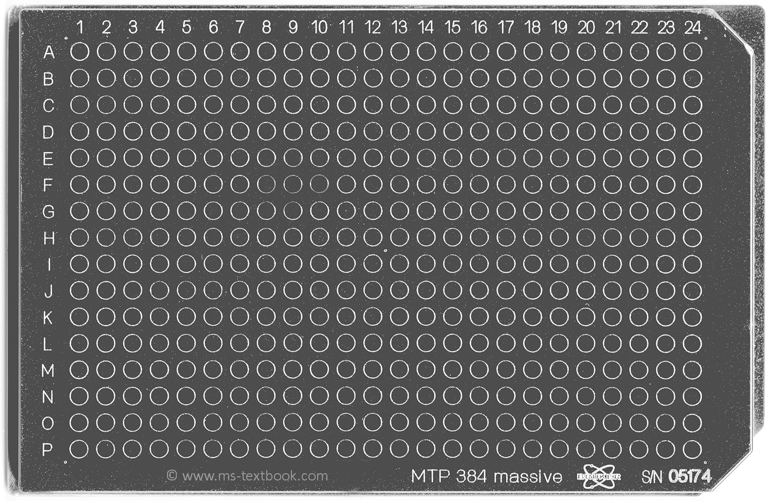
Fig. 11.12 Typical MALDI target: Bruker Scout384™target offers a 16 � 24 spot array with up to 384 positions for sample preparation. Here, a standard nickel-coated massive aluminum version is shown; its dimensions are 84 � 128 mm with engraved marks of 3 mm in diameter.
Fig. 11.13 Sample preparation for MALDI. (a) Pipetting of 1 μl of sample–matrix solution onto a standard MALDI target; (b) same spots after DHB has crystallized show large crystals on the rim and evenly distributed small crystals in the center; (c) cummulative effect of hydrophilic spots (bright areas in circles) present on a hydrophobic surface of an AnchorChip™ target on crystallizing DHB matrix.
Fig. 11.25 NEW Procedure to measure oligosaccharides of a gummy bear by MALDI-MS. (The
resulting spectrum is shown in Fig. 11.26.)
Chapter 13
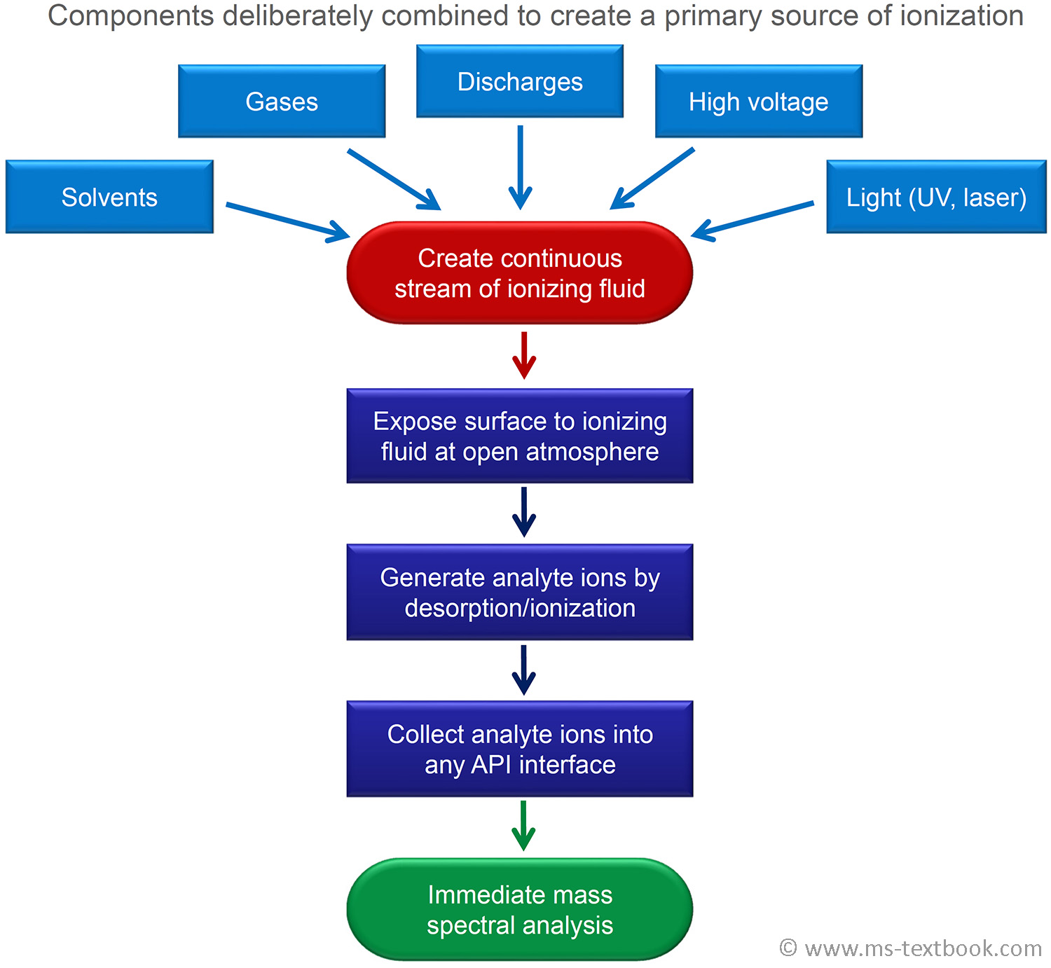
Fig. 13.1 NEW Concept of ambient desorption/ionization mass spectrometry.
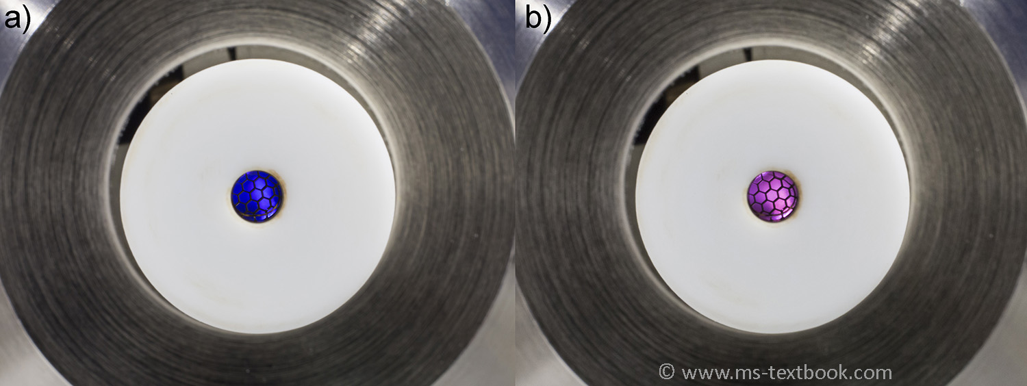
Fig. 13.26 NEW DART discharges as seen when looking into the source. (a) Blue shining discharge in nitrogen, (b) pale pink discharge in helium. The hexagonal pattern is caused by the exit grid electrode.
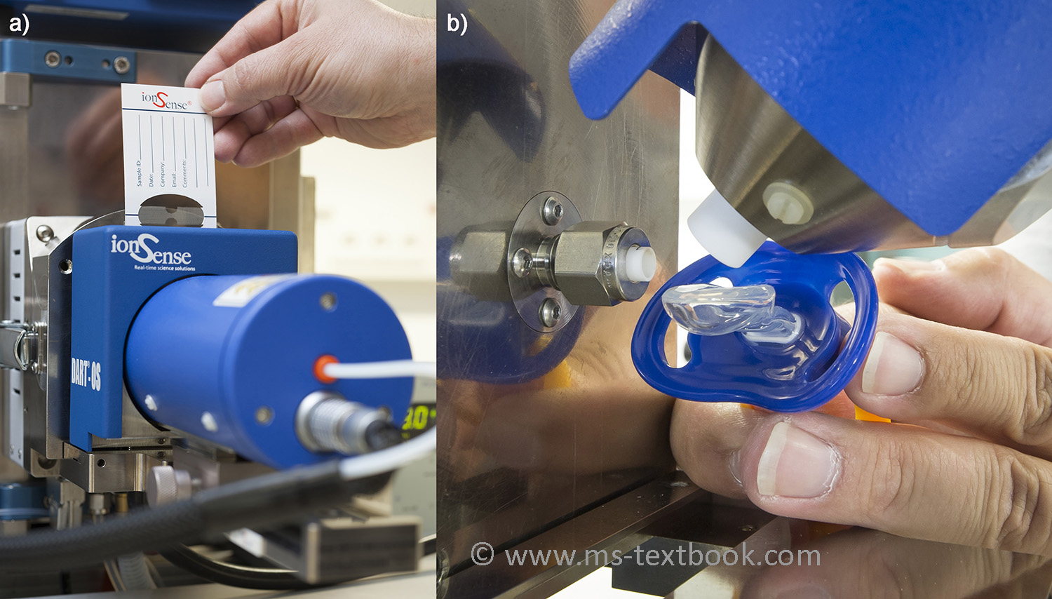
Fig. 13.30 NEW DART configurations in use. (a) Open Source for transmission mode DART with disposable sample cards, (b) alignment at an angle of 45� for the analysis of objects placed in the gap. Both photos show the DART source attached to a Bruker instrument by means of the Vapur Interface.
Chapter 14
Fig. 14.3 NEW Fused-silica capillary column for gas chromatography on a coil of about 20 cm in diameter. The golden color is caused by the outer polyimide coating of the silica capillary.
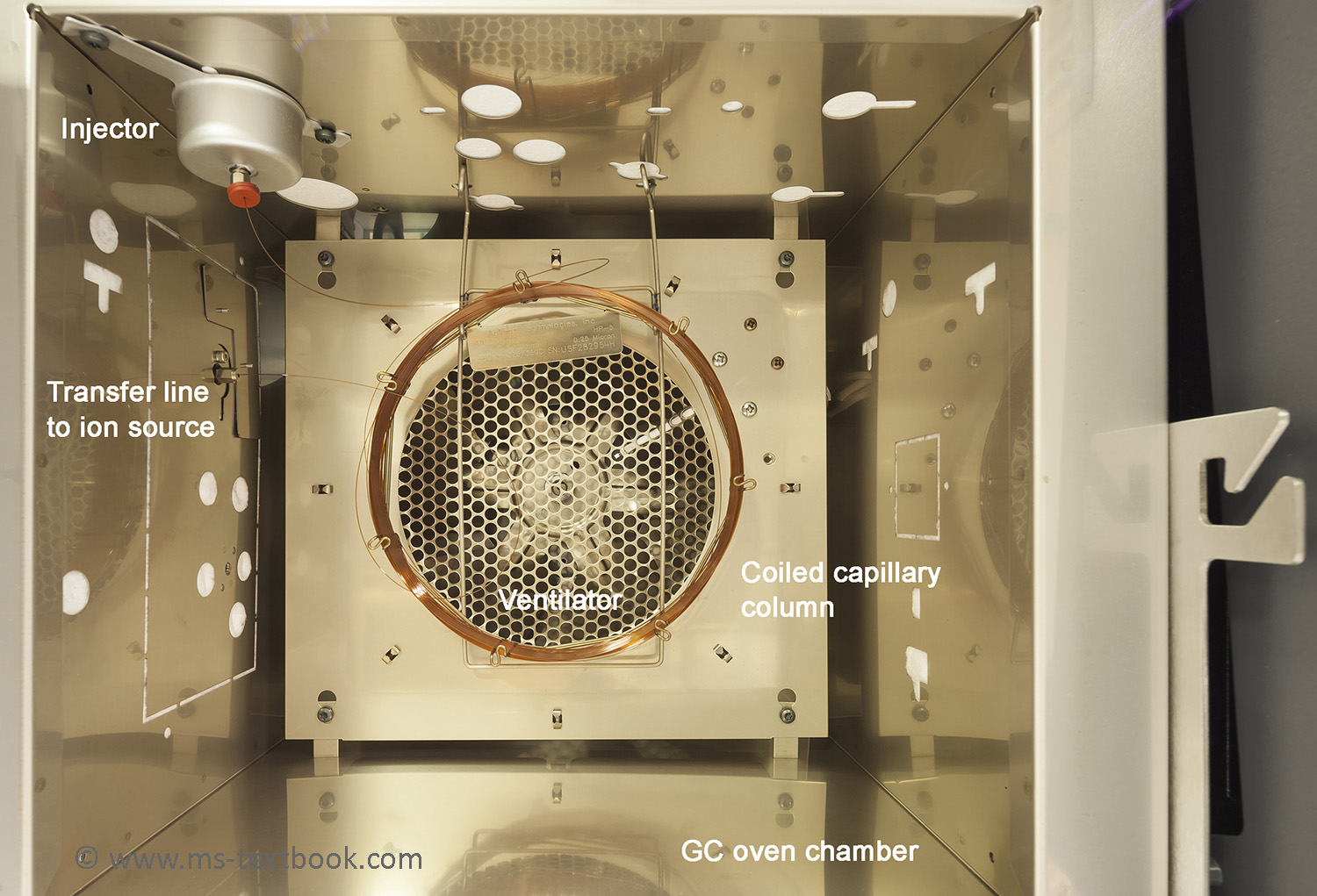
Fig. 14.4 NEW GC oven for capillary gas chromatography with open front door. The GC column
wound onto a coil is suspended to hang freely in the heated air.
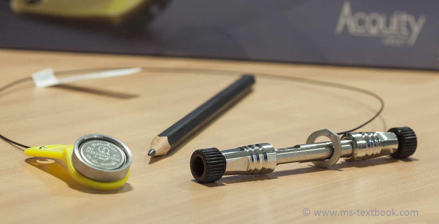
Fig. 14.8 NEW UPLC column. The actual column (right), here shown with the two end caps still in place, is quite small as by comparison to the pencil. This particular column is a Waters BEH C18 reversed phase type of 50 mm length and 2.1 mm inner diameter filled with 1.7-μm-sized particles.
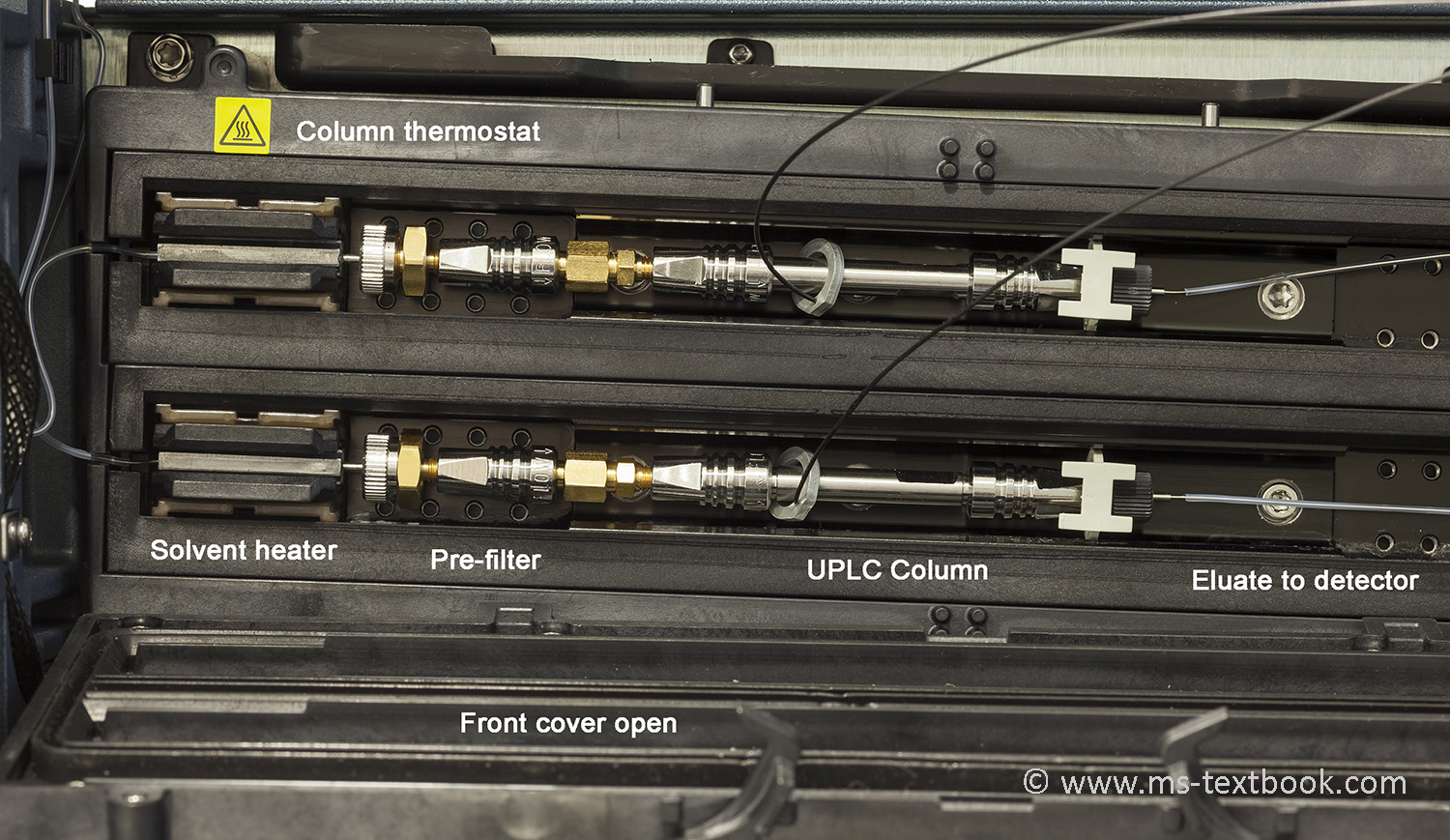
Fig. 14.10 NEW A column thermostat of a Waters Acquity system with two UPLC columns mounted inside. The sample solution first passes a heater cartridge to ensure constant temperature equal to that of the column, then a pre-filter to prevent the column from clogging, and finally enters the UPLC column.